



Fehlausrichtung des Stiftstifts: Symptome und Fehlerbehebung
Mold positioning pin misalignment can cause binding during closure, Ungleichmäßiger Kontakt, parting-line mismatch, Flash, abnormal wear, or inconsistent part dimensions. The pin itself may be damaged, aber es ist nur eine mögliche Ursache. A worn bushing, loose mounting bore, contaminated parting surface, damaged interlock, Thermisches Wachstum, poor mold installation, or machine-platen condition can create similar symptoms.
The correct approach is to identify when the problem occurs, inspect the entire mating system, measure the suspected geometry, and repair only the verified cause. For broader information about component fit, Verschleiß, Materialien, und Schmierung, see SunshinePro’s guide to Formstifte und Buchsen (Schlussfolgerung).
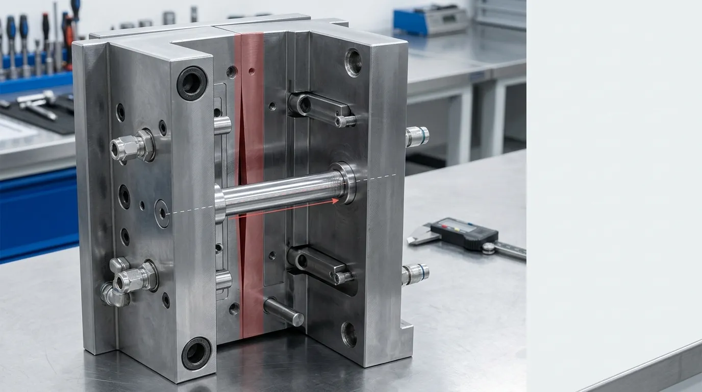
Bestätigen Sie zuerst, was der "Positionierungsstift" in dieser Form bewirkt
“Positioning pin” is not used consistently across every mold design. Before troubleshooting, identify the component by function rather than relying only on its name.
| Komponente | Hauptrolle | Diagnostische Implikation |
|---|---|---|
| Ortungs- oder Dübelstift | Stellt eine wiederholbare Position zwischen Komponenten oder Platten her | Check its geometry, mounting fit, Orientierung, and mating hole or bushing |
| Leitnadel, leader pin, oder Führungssäule | Führt die Formhälften während des Engagements | Überprüfe die Geradlinigkeit, Verschleiß, bushing clearance, and side-loading marks |
| Führungs- oder Ortungsbuchsen | Nimmt den Stift auf und steuert die Koppelschnittstelle. | Check bore wear, ovality, Position, Verbleib, and entry damage |
| Seitenverriegelung oder Kegelverriegelung | Hilft bei der Festlegung oder Aufrechterhaltung der endgültigen Schimmelregistrierung | Check contact pattern, Verschleiß, Schäden, und Einsatz |
| Abschalt- oder präzise Verbindungsfläche | Trägt zur endgültigen Ausrichtung und Abdichtung bei | Check for impact marks, Fehlanpassung, local gaps, and edge damage |
A guide pin may control the initial closure path while another locating feature controls final core-to-cavity registration. Replacing the guide pin will not solve the problem if the final interlock, Buchsen, mounting bore, or mold plate is out of position.
SunshinePros separater Leitfaden zu Formführungsstifte covers broader guide-pin function, Verschleiß, und Auswahl. Hier, the focus is determining why an installed mold is no longer aligning correctly.
Symptome, die auf ein Schimmelregistrierungsproblem hinweisen
The timing and location of a symptom often provide more useful evidence than the symptom alone.
| Symptom | Wenn es erscheint | Mögliches Teilsystem | Erste Bestätigungsprüfung |
| Binden am selben Punkt während des Schließens | Kalt- oder Nicht-Last-Verschluss | Gebogener Stift, skewed bushing, damaged interlock, Gratling, or plate-position error | Halten Sie am ersten Kontaktpunkt an und inspizieren Sie nach einseitigen Zeugenspuren |
| Scraping, Vibration, or impact noise | Während des Stift- oder Verriegelungseinsatzes | Seitenbelastung, insufficient clearance, Kontamination, or damaged entry geometry | Inspect the pin, bushing mouth, interlocks, and nearby surfaces |
| Abnormale Hitze in der Nähe des Führungssystems | Nach wiederholtem Einfahren | Reibung, Schlechte Schmierung, tight fit, Seitenbelastung, or galling | Überprüfen Sie die Punktzahl, Verfärbung, Schmierstoffzustand, and uneven contact |
| Schimmel schließt sich nicht genau | Aufbau oder kontrolliertes Schließen | Mounting error, Behinderung, Plattenverzerrung, machine-side alignment, or damaged positioning components | Inspect mounting, Ortungsmerkmale, parting surfaces, and plate relationships |
| Trennlinie-Schritt oder Mismatch | Während der Produktion | Registration loss, Plattenbewegung, interlock wear, or machine-side loading | Vergleichen Sie die Fehlanpassungsposition mit Kontakt- und Verschleißmustern |
| Lokalisierter Blitz | Unter Einspritzdruck | Misregistration, damaged shutoff, insufficient clamping, Kontamination, or process conditions | Überprüfen Sie, ob der Schimmel sich druckfrei ausrichtet, und inspizieren Sie den betroffenen Absperrer |
| Dimensionsvariation zwischen Zyklen | Nach dem Aufwärmen oder unter Last | Changing clearance, Thermisches Wachstum, Plattenbewegung, or worn positioning features | Compare cold, warm, and production-condition measurements |
| Einseitiges Stift- oder Buchsenpolieren | Fortschrittlich im Laufe der Zeit | Mispositioned bore, bent pin, plate error, or uneven machine loading | Messen Sie den Stiftauslaufen und inspizieren Sie die Position und Senkrechte des Bohrers |
DME’s technical guidance on mold interlocks identifies flash, dimensional problems, and component damage as possible consequences of improper mold alignment. It also notes that worn leader pins and bushings, thermal variation, mold weight, and equipment condition can affect registration. See DME’s Technische Leitlinien zur Formausrichtung.
Flash alone does not prove positioning pin failure. Flash can also result from damaged shutoffs, trapped material, insufficient clamping, Übermäßiger Druck, or other tooling and process conditions. Treat it as evidence that requires further inspection.
Symptome während des Schimmelschließens
Closure-related symptoms usually point toward the engagement path.
Suchen Sie nach:
- Resistance that begins at the same position during each closing attempt.
- A pin entering the bushing off-center.
- Fresh contact marks on only one side of the pin.
- Scraping at the bushing entrance.
- Impact marks on interlocks or shutoffs.
- A visible gap on one side of the parting line.
- A pin, Buchsen, or retainer moving in its mounting feature.
A repeatable hard-contact point is more likely to involve geometry, Behinderung, or mounting position than a process-setting problem.
Symptome auf dem geformten Teil oder der Trennfläche
Production evidence may include:
- A step across the parting line.
- Flash concentrated in one region.
- Uneven witness lines.
- Chipping or peening near a precision shutoff.
- Dimensional changes after the mold reaches operating temperature.
- Parts that shift in one direction under pressure but appear acceptable during an unloaded closure check.
These symptoms help locate the affected region, but measurements are still needed before deciding which component to repair.
Hören Sie auf, den Schimmel zu zyklieren, wenn Schäden wahrscheinlich sind
Do not continue closing the mold to “see if it clears” when there is evidence of hard interference or displaced components.
Stop and establish a safe inspection condition when you find:
- A visibly bent or loose pin.
- A cracked, gechippt, or displaced bushing.
- Metal fragments or severe scoring.
- Fresh impact damage on a core, Hohlraum, Insert, shutoff, or interlock.
- Sudden hard resistance during closure.
- A plate or component moving inside its mounting feature.
- An engagement path that cannot be confirmed safely.
Injection molding machines can expose technicians to crushing, stored hydraulic energy, electrical energy, hot surfaces, and moving components. Inspection and servicing should follow the machine manufacturer’s instructions, the facility’s hazardous-energy procedure, and applicable local regulations. Die USA. Occupational Safety and Health Administration provides general guidance on Horizontale Spritzgussmaschinen-Gefahren und Steuerung gefährlicher Energie.
Fehlerbehebung von Fehlausrichtungen in einer festen Reihenfolge
A consistent sequence reduces unnecessary disassembly and prevents one symptom from being mistaken for proof of pin failure.
- Review when the problem started.
Determine whether the change was sudden or progressive. Check whether it began after maintenance, Bauteilersatz, mold transfer, machine setup, a cooling change, or warm-up. - Place the machine and mold in an approved safe inspection condition.
Isolate hazardous energy before entering the mold area or touching components that could move. - Clean exposed interfaces.
Remove trapped plastic, Chips, Mahlscheiben, contaminated lubricant, and other debris from the parting line, pin entries, Buchsen, and interlocks. - Inspect the pin, Buchsen, Montage, and retention.
Look for looseness, Punktewertung, impact marks, ungleichmäßiges Polieren, Verdrängung, or damaged fasteners. - Observe the engagement pattern.
Under an approved controlled procedure, identify which component contacts first and whether the contact is centered or one-sided. - Measure the suspected geometry.
Check pin and bushing dimensions, Runout, Zustand der Montagebohrung, component position, and plate relationships. - Separate mold-side causes from machine-side and thermal causes.
Compare cold and warm behavior, unloaded and production-loaded behavior, and results across machines when practical. - Correct the verified cause.
Clean, adjust, Reparatur, or replace only after the inspection evidence supports that action. - Validate the repair.
Confirm smooth engagement, stable registration, correct parting-line contact, and acceptable molded-part results.
Record, wann das Problem begann
The failure history can quickly narrow the investigation.
A sudden problem after maintenance may indicate:
- A reversed or incorrect replacement component.
- A bushing or pin installed at the wrong depth.
- A burr created during assembly.
- A loose retainer or fastener.
- A plate assembled out of position.
Progressive deterioration more often suggests:
- Increasing pin or bushing wear.
- Lubrication breakdown.
- Mounting-bore damage.
- Plate movement.
- Repeated side loading.
- Thermal or machine conditions that gradually accelerate wear.
A problem that appears only after moving the mold to another machine should trigger checks of mold installation, locating-ring engagement, platen condition, and clamping alignment before replacing mold components.
Beginnen Sie mit Reinigung und zerstörungsfreier Inspektion
Begin with checks that do not alter the mold:
- Clean pin surfaces and bushing entrances.
- Remove plastic residue from the parting line.
- Inspect for burrs around bores and interlocks.
- Check retainers and fasteners for movement.
- Mark and photograph contact patterns.
- Compare the left and right sides of the mold.
- Check whether the pin enters the bushing concentrically.
Cleaning may restore movement when debris is the only obstruction. It does not prove that the pin, Buchsen, or plate geometry remains within specification.
Inspizieren Sie den Pin, Buchsung, and Mounting Features as One System
A positioning pin does not work independently. Its performance depends on the mating bushing or hole, the mounting bore, the mold plate, and any final-positioning features.
Hinweise zum Scheitern auf der Stiftseite
Evidence that directly implicates the pin includes:
- Measurable bending or runout.
- One-sided scoring along the engagement length.
- Impact damage at the leading end.
- Mushrooming or chipped edges.
- A loose shank or failed retaining feature.
- Incorrect installed height.
- Geometry that does not match the drawing.
- Contact concentrated in one region rather than distributed as intended.
One-sided polishing can indicate a bent pin, but it can also result from a mispositioned bushing or mounting bore. Confirm the pin’s straightness before assigning the cause.
Buchsung- and Bore-Side Failure Clues
Inspect the mating side for:
- Uneven or oval bore wear.
- A loose bushing.
- Damage at the entry chamfer.
- Scoring concentrated on one side.
- A bushing installed out of position.
- Cracks or deformation around the mounting feature.
- A damaged press-fit bore.
- Burrs that prevent the bushing from seating correctly.
Replacing a worn pin while leaving an oval or loose bushing in place may restore movement temporarily without restoring repeatable registration. The mating pair and both mounting features should be evaluated together.
Missen Sie die Geometrie, bevor Sie eine Reparatur auswählen
Visual inspection identifies where to investigate, but dimensional evidence should determine whether a component is acceptable.
Measure as applicable:
| Merkmal | Warum es wichtig ist | Akzeptanzbasis |
| Stiftdurchmesser an mehreren Positionen | Reveals taper, localized wear, or material loss | Genehmigte Formzeichnung oder Bauteilspezifikation |
| Buchsbohrung in mehreren Ausrichtungen | Identifiziert übermäßigen Abstand oder ovalen Verschleiß | Zeichnung, supplier specification, or applicable standard |
| Pin-Geradeausheit oder Runout | Erkennt Biegen, die progressiven Seitenkontakt verursacht | Zeichnung oder genehmigtes Inspektionsverfahren |
| Position von Stift und Buchse | Bestimmt, ob ihre Achsen ausgerichtet sind | Formzeichnung und Bezugsstruktur |
| Senkrecht zur Platte | Identifiziert geneigte Montage oder Bohrungsfehler | Zeichnung oder technische Spezifikation |
| Zustand der Montagebohrung | Bestimmt, ob die Komponente korrekt unterstützt und erhalten bleibt | Zeichnung und genehmigte Reparaturkriterien |
| Plattenbeziehung | Detects shift, Verzerrung, or movement between assemblies | Gussbau-Zeichnung und Inspektionsplan |
Do not apply one universal pin-to-bushing clearance or wear limit to every mold. The correct value depends on the component design, Größe, Funktion, supplier series, Betriebstemperatur, and required positioning accuracy.
For standardized components within their stated scope, ISO 8017 covers dimensions and tolerances for specified guide pillars and locating guide pillars. ISO 8018 covers specified headed guide and locating guide bushes. These standards do not replace the approved mold drawing, and they should not be applied to components outside their scope.
Record the measurement reference, Instrument, Aufbau, Zeichnungsrevision, and actual results. A list of numbers without the measurement method may not be sufficient for repair or replacement decisions.
Getrennte Guss-Ursachen von maschinellen und Temperatureinflüssen
The same mold symptom can originate outside the pin-and-bushing pair.
Ask:
- Did the problem begin after installing the mold on a different machine?
- Does the mold align when cold but bind after warm-up?
- Does it close smoothly without pressure but shift during production?
- Is one mold half operating at a different temperature?
- Are the locating ring and mounting surfaces seated correctly?
- Are the platens, Klemmen, or tie system applying uneven load?
- Do interlocks show contact only after pressure is applied?
- Does the problem disappear when the mold is checked outside the original machine?
Kalt- versus heiße Fehlausrichtung
A mold may close correctly at room temperature and begin binding after thermal stabilization. Unequal heating changes the dimensions of plates, bores, Pins, Buchsen, and interlocks. The pin may appear to be the problem even though the underlying cause is differential thermal growth.
Compare:
- Cold engagement.
- Engagement during warm-up.
- Stable operating-temperature engagement.
- Temperatures on both mold halves.
- Cooling conditions near the affected region.
- Contact marks before and after warm-up.
Do not assume the pin changes independently of the surrounding plate. The entire alignment chain expands and moves together.
Nicht-Last- versus Unterdruck-Fehlausrichtung
Smooth unloaded closure does not guarantee stable registration during production.
If misalignment appears only under injection or clamping load, Inspizieren:
- Side interlocks and taper locks.
- Plate support and fasteners.
- Shutoff contact.
- Mold mounting.
- Platen condition.
- Locating-ring engagement.
- Load-sensitive movement between plates.
Changing pressure, Geschwindigkeit, or clamping settings may reduce the visible defect, but it does not correct a mechanical positioning error.
Gleiche die Korrekturmaßnahme der verifizierten Ursache an
| Verifizierte Ursache | Angemessene Maßnahmen | Zusätzliche Überprüfung |
| Trapped plastic, Chips, or removable debris | Reinigen Sie die betroffenen Oberflächen | Bestätigen Sie, dass kein Grat oder bleibender Schaden vorhanden ist |
| Kontaminiertes oder fehlendes zugelassenes Schmiermittel | Reinigen und stellen Sie den angegebenen Schmierzustand wieder her | Inspect for existing scoring, Verschleiß, or galling |
| Bent, worn, or impact-damaged pin | Ersetzen Sie durch ein Bauteil, das der genehmigten Zeichnung entspricht | Inspizieren Sie die Buchse und die Montagebohrung |
| Abgenutzte oder ovale Buchse | Ersetzen oder reparieren Sie entsprechend dem Schimmeldesign | Bestätigen Sie den Zustand des Stifts und die tatsächliche Passfreiheit |
| Locker Stift oder Buchse | Korrigieren Sie die Befestigungs- oder Befestigungsfunktion durch eine genehmigte Reparatur | Überprüfe, ob der Bohr oder die Platte beschädigt ist |
| Beschädigte Montagerohr | Reparieren Sie die Bohrung oder die betroffene Platte, bevor Sie ein neues Bauteil einbauen | Wiederherstellung von Position und Senkrecht |
| Abgenutzte Verriegelung oder Abschaltung | Reparatur oder Austausch der betroffenen Endpositionierung | Bestätigen Sie, dass die Führungskomponenten nicht seitlich geladen wurden |
| Installations- oder Lokalisierungsringfehler | Korrekte Montage und Zentrierung der Form | Erneute Schließung und Kontakt der Trennlinie |
| Maschinenseitige Ladung oder Plattenproblem | Folgen Sie dem Inspektions- und Reparaturprozess des Maschinenherstellers | Bestätigen Sie, dass der Schimmel keine Sekundärschäden erlitten hat |
| Thermische Verzerrung | Korrigiere das verifizierte Temperatur- oder Kühlungleichgewicht | Validierung der Ausrichtung bei stabiler Betriebstemperatur |
Lubrication can reduce friction. It cannot straighten a bent pin, correct a misplaced bore, restore an oval bushing, or realign a distorted plate.
Do not install a new pin into a damaged bore simply because the replacement fits initially. If the mounting feature cannot hold the component at the required position and angle, the new part may fail quickly or reproduce the same alignment error.
Überprüfen Sie die Ausrichtung, bevor Sie die Form wieder in die Produktion bringen
After correction, validate the complete system rather than checking only whether the mold can close once.
Use the machine manufacturer’s approved procedure to confirm:
- Smooth and repeatable engagement.
- No abnormal impact, scraping, Vibration, or resistance.
- No new scoring or concentrated witness marks.
- Correct parting-line and shutoff contact.
- Stable pin and bushing temperatures.
- No movement at retainers or mounting features.
- Consistent behavior after the mold reaches operating temperature.
- Stable registration under approved production conditions.
- Acceptable molded-part dimensions.
- No abnormal flash or parting-line step.
Recheck critical dimensions when a pin, Buchsen, Bohrung, Kennzeichen, or interlock has been repaired. Record what was changed, the measurements taken, and the validation result. One successful closing cycle is not sufficient evidence of long-term correction.
Bereite vollständige Austauschinformationen vor, wenn ein Bauteil außerhalb der Spezifikation ist
Once inspection confirms that a positioning pin, guide component, or bushing requires replacement, provide the supplier with enough information to reproduce the intended geometry rather than the worn condition.
Bereiten Sie sich vor:
- The approved component drawing and revision.
- The component’s function: Lokalisierung, Führung, or final positioning.
- Pin and mating-bushing dimensions.
- Mounting and retention details.
- Required fit and tolerances.
- Material, Härte, Wärmebehandlung, and surface requirements stated on the drawing.
- Menge.
- The worn sample, when useful and available.
- Photographs or notes showing the failure pattern.
- Confirmation of whether the mating component or mounting bore will also be repaired.
- Required inspection documentation.
SunshinePro gibt an, dass es sowohl standard- als auch zeichenbasierte Maßanfertigungen anbietet Formstandardteile, including guide components and dowel pins. The company also lists locating-pin guide bushings and describes inspection processes for custom components.
After the failed component and its mating conditions have been measured, the next practical step is to Reichen Sie die Zeichnung und die Ersatzanforderungen ein zur Überprüfung. The request should describe the verified failure and required geometry rather than asking a supplier to reproduce an unmeasured worn sample.
Teilen:



Geschrieben von Sunshine
Bei Sunshine, Wir sind ein professioneller Hersteller und Lieferant von Präzisionsformkomponenten, bietet ein breites Produktsortiment für Stange- und Spritzgussanwendungen. Unser Kernfokus liegt auf dem Stanzen von Stempeln, Auswurfstifte und -hülsen, sowie Führungspfosten und Buchsen. Mit fortschrittlicher CNC-Bearbeitung, Strenge Qualitätskontrolle, und starke Produktionskapazitäten, Wir sorgen für Zuverlässigkeit, Hochpräzisionsteile, zusammen mit vorrätigen Standardkomponenten für schnelle und effiziente weltweite Versorgung.
NACHRICHTEN
EMPFANG SERVICE
Mit hochwertigen Teilen für jedes Budget und freundlichem Personal, das geschult ist, um Ihren Besuch informativ und unkompliziert zu gestalten.
